
Resistivity surveys measure the capacity of the ground to pass an electrical current. This property can be utilised for designing earthing systems for substations or specialist plant, and for measuring the corrosion susceptibility of buried pipelines and other steel structures. Four equidistant electrodes are set-out in a fixed configuration array; a low frequency current is applied across the two outer electrodes with the resultant voltage measured across the inner electrodes. The reading is converted by standard equations into a value representing the average resistivity of the ground between the electrodes. Resistivity depth readings are acquired by electrical soundings using an expanding electrode array centred on the same point. The depth penetration of the readings is directly proportional to the electrode spacing. Our company provides a variety of resistivity testing services for engineering infrastructure, new plant and generator installation and electricity substations:

Earth rod testing using a 2-electrode resistivity system
Earthing systems provide a safe connection between an electrical circuit and the ground. They are used for the dissipation of electrical faults, grounding lightning strikes and maintaining the correct operation of electrical equipment. The correct design of an earthing system is dependent upon detailed knowledge of the local ground resistivity. This is measured as a function of depth at a series of locations around the site, using an expanding four electrode Wenner array (BS EN 50522). The procedure is known as soil resistivity or earth resistance testing. Correct measurement is particularly important in areas of high resistivity ground, where electrical currents are not able to dissipate. In these conditions obtaining an earth can be problematic, and information on ground resistivity is required to much greater depths for the successful installation of an earthing system .
The resistance of an installed earth rod can also be tested to verify an earthing system. Using a specially adapted testing procedure, the earth rod is connected with a two-electrode resistivity system (IEEE 81). The electrodes are configured so that the system measures the resistance of the earth rod directly.

Soil resistivity testing with a 4-electrode Wenner array
A knowledge of soil corrosivity is critical for the design of cathodic protection measures, or predicting the effective lifetime of a steel structure such as a tank that is to be buried within the ground. Factors such as soil composition, moisture content, pore water chemistry, pH and redox potential (see below) control the ground resistivity, which is the main diagnostic factor.
Using a four-electrode resistivity system (BS 1377), specific sections of a proposed pipeline route are targeted to measure the resistivity of each lithology encountered, and investigate special situations such as fault zones or infilled channels. Surveys are designed to take readings down to pipeline depth. Deeper readings are required near water courses and other cross-overs where the pipeline has to be embedded at greater depths. The resultant resistivity data is converted into corrosivity factors and integrated into the design of effective cathodic protection measures.
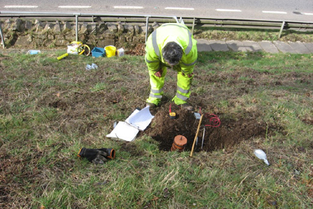
Soil redox testing on the side of a road cutting
An important component of soil corrosivity assessment involves the measurement of soil redox potential. This measures the ability of a soil to ionise,by the transference of electrons either to or from a reference electrode. The measurement data indicates if the soil is aerobic or anaerobic, and whether iron oxides or nitrates in the soil have been reduced or are present in an oxidized form.
The in-situ soil redox measuring system consists of a high impedance voltmeter, a platinum test electrode and a silver reference electrode (BS ISO 11271). The electrodes are inserted at a set level in the ground below root level, then the magnitude and polarity of the potential between the platinum and reference electrodes is measured. Results are corrected for soil temperature and then converted to into a standard form as a hydrogen electrode equivalent, termed the redox potential (Eh).
Phone us at: +44-1905-619531 or e-mail us at: [email protected]