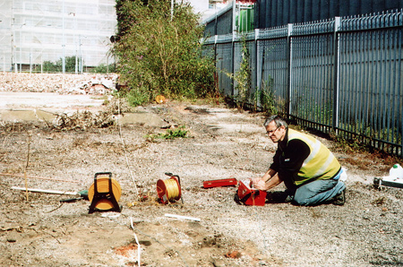

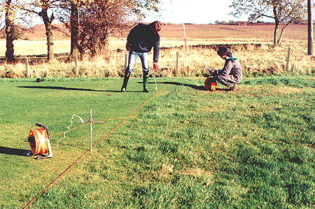
Ground resistivity surveys measure the capacity of the ground for passing an electrical current. This property can be used for measuring the corrosion susceptibility of a buried pipeline, or planning the installion of an earthing system. Standard resistivity surveys use four equidistant electrodes spaced in a fixed configuration. A low frequency current is applied across the outer two electrodes and the resultant voltage is measured across the inner electrodes. The voltage reading is converted by standard equations into a resistivity value, representing the average resistivity of the ground between the electrodes. To take resisitivty depth readings, electrical soundings are taken using an expanding electrode array centred on the same point. The depth penetration of the readings is directly proportional to the electrode spacing.
|
|
Earthing systems provides a safe connection between an electrical circuit and the ground. They are used for the dissipation of electrical faults, grounding lightning strikes and maintaining the correct operation of electrical equipment. Proper design of an earthing system requires knowledge of the ground resistance. This is done by resitivity testing using an expanding 4-electrode array, which measures resisitivity as a function of depth at a series of locations. Earth testing is particularly important in areas of high resistivity ground where currents do not readily dissipate. Obtaining an earth in these conditions is problematic, requiring information on ground resistivity to much greater depths.
The resistance of an installed earth rod can also be tested to verify the earthing system. Using a specially adapted testing procedure, the earth rod is connected with a two electrode resistivity system. The electrodes are configured so that the resistance of the earth rod is measured, but not that of the surrounding ground.
|
A knowledge of soil corrosivity is critical for the effective design of cathodic protection measures or predicting the lifetime of a buried steel structure. Factors such as soil composition, moisture content, pore water chemistry and pH control the ground resistivity, which is the main diagnostic factor.
Specific sections of a proposed pipeline route are targeted to measure the resistivity of each lithology encountered and investigate special situations such as fault zones or infilled channels. Surveys are designed to take readings down to pipeline depth. Deeper readings are required near water courses and other cross-overs, where the pipeline has to be embedded at greater depths. The resultant resistivity data is converted into corrosivity factors and integrated into the design of effective cathodic protection measures.